Table of Contents

Search

  1. Preface
  2. Introduction
  3. Configuring the Data Director Application
  4. Establishing a Root Node
  5. Defining the Business Entity Model
  6. Configuring Business Entity Properties
  7. Configuring Reference Entity Properties
  8. Transforming Business Entities and Views
  9. Managing Many-to-Many Relationships
  10. Configuring Search
  11. Configuring Workflow Tasks and Triggers
  12. Configuring Security and Data Filters for Business Entities
  13. Integrating Data as a Service
  14. Configuring External Calls
  15. Designing the Data Director User Interface
  16. Localizing Data Director
  17. Provisioning Tool Frequently Asked Questions

Configuring a Relationship

Configuring a Relationship

When you configure a relationship between business entities, you create a relationship between two base objects. Create a relationship between two business entities in the Provisioning tool.
  1. Log in to the Provisioning tool and select the ORS.
  2. Click
    Business Entity
    Modeling
    .
  3. From the
    Modeling
    list, select
    Relationships
    , and then click
    Create
    .
    The fields that you must configure appear in the
    Properties
    panel.
  4. In the Properties panel, specify the following relationship properties:
    Property
    Description
    Name
    Unique name for the relationship.
    Label
    Label for the relationship that appears in the
    Data Director
    user interface.
    Description
    A meaningful description for the relationship.
    Display name
    Name that appears in the Entity layout.
    Bi-directional
    Indicates whether the direction of the relationship goes both ways.
    State Management Enabled
    Indicates whether state management is enabled.
  5. From the
    Base object
    list, select a base object from the MDM schema that will maintain the relationship between the two base objects.
  6. In the
    Parent Business Entity
    list, select the base object, which is the first entity in the relationship.
  7. In the
    Parent Constraint
    field, select the column to which the foreign key points.
  8. From the
    Child Business Entity
    list, select the base object, which is the second entity in the relationship.
    The
    Parent Business Entity
    and the
    Child Business Entity
    specify the direction of the relationship.
  9. In the
    Child Constraint
    field, select the column to which the foreign key points.
  10. Optionally, if you want to show the labels on the UI, select the
    Label Format
    check box and specify the following properties:
    Property
    Description
    Exists format
    Title that appears when you view the relationship.
    No fields format
    Title to display when all the fields in the Exists Format have NULL values.
  11. Click
    Apply
    .
    The relationship appears in the root node panel.
  12. To add additional attributes for the relationship, specify the fields that will appear in the user interface when creating or viewing the relationship:
    1. Select
      Fields
      under the tree node, and click
      Create
      .
    2. Specify the following properties:
      Property
      Description
      Name
      Name for the field.
      Label
      Display name for the field in the user interface.
      Read Only
      Indicates whether the field is read only.
      Required
      Indicates whether you must specify the field when you create a relationship.
      URI
      URI for where your custom data types are defined, if you want to associate a custom data type with the business entity field,
      Type
      Name of the custom data type that you define in the URI. Used with the URI property.
      Column
      Business entity field.
      Searchable
      Indicates whether the field is searchable.
      If you enable the Searchable property, the Searchable Configuration fields appear.
      Filter
      Regulates the data that users can enter in the field.
      If you enable the Filter property, the properties related to filter behavior appear. Specify the filter behavior property and the filtered value.
      Operator
      Specify
      IN
      to ensure that filter values are the only values allowed in the field. Specify
      NOT_IN
      to ensure that filter values are not allowed in the field.
      Value
      Filter value.
    3. Click
      Apply
      .
    4. Repeat Steps
      a
      to
      c
      for each field you want to add as additional attribute to the relationship.
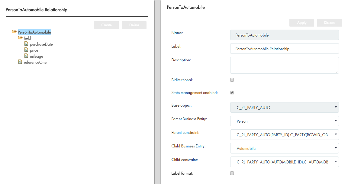
The following image shows a sample business entity relationship configuration with fields for additional attributes: Business entity relationship configuration with a fields for the attributes.

0 COMMENTS

We’d like to hear from you!