Table of Contents

Search

  1. Preface
  2. Welcome to Informatica Process Developer
  3. Using Guide Developer for the First Time
  4. Getting Started with Informatica Process Developer
  5. About Interfaces Service References and Local WSDL
  6. Planning Your BPEL Process
  7. Participants
  8. Implementing a BPMN Task or Event in BPEL
  9. Implementing a BPMN Gateway or Control Flow
  10. Using Variables
  11. Attachments
  12. Using Links
  13. Data Manipulation
  14. Compensation
  15. Correlation
  16. What is Correlation
  17. What is a Correlation Set
  18. Creating Message Properties and Property Aliases
  19. Adding a Correlation Set
  20. Deleting a Correlation Set
  21. Adding Correlations to an Activity
  22. Rules for Declaring and Using Correlation Sets
  23. Correlation Sets and Engine-Managed Correlation
  24. Event Handling
  25. Fault Handling
  26. Simulating and Debugging
  27. Deploying Your Processes
  28. BPEL Unit Testing
  29. Creating POJO and XQuery Custom Functions
  30. Custom Service Interactions
  31. Process Exception Management
  32. Creating Reports for Process Server and Central
  33. Business Event Processing
  34. Process Central Forms and Configuration
  35. Building a Process with a System Service
  36. Human Tasks
  37. BPEL Faults and Reports

Designer

Designer

Flow

Flow

The Flow container is displayed in Process Developer Classic layout style. If the BPMN style is in effect, there is no Flow container in the palette. The equivalent container is called Fork Join.
A Flow container executes all activities in parallel. This means you can define two or more activities, such as two Receive activities, to start at the same time. The activities start when the flow starts. The flow completes when all the activities in the container have completed.
For example, you can receive approval from both a seller and a buyer by adding the seller and buyer receive activities to a flow. Both receives must complete before the process executes another activity, such as invoking an order shipment service.
Flows can also contain links that allow you to introduce dependencies between activities to control the order in which they are executed. Refer to
Using Links
for more information.
The Flow is most useful for concurrent execution of activities.
Required Properties
Optional Properties
none
Name. See
Selecting Activity Labels
Join Condition. See
Creating a Join Condition for an Incoming Link
Suppress Join Failure. See
Process Properties
Comment. See
Adding Comments to a Process
Documentation. See
Adding Documentation to a Process
Setting Visual Properties and Using Your Own Library of Images
Execution State. See
Viewing the Execution State of an Activity or Link
Extension Attributes and Extension Elements. See
Declaring Extension Elements and Attributes
.
To build a flow:
  1. Ensure that the layout style preference is set to Process Developer Classic.
  2. From the
    Container
    palette, drag a F
    low
    to the Process Editor canvas.
  3. Drag an activity, such as Receive, inside the Flow.
  4. Continue dragging the other activities into the Flow to execute concurrently.
  5. Specify all the properties for each activity in the Flow.
The following illustration shows an example of a Flow activity.
XML Syntax
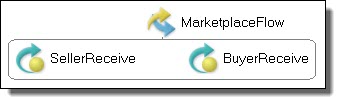
<flow atandard-attributes> standard-elements <links>? <link name="ncname">+ </links> activity+ </flow>
Example:
<flow name="MarketplaceFlow"> <receive name="SellerReceive" partnerLink="seller" portType="tns:sellerPT" operation="submit" variable="sellerInfo" createInstance="yes"> </receive> <receive name="BuyerReceive" partnerLink="buyer" portType="tns:buyerPT" operation="submit" variable="buyerInfo" createInstance="yes"> </receive> </flow>

0 COMMENTS

We’d like to hear from you!