Process Developer Classic style is supported primarily for legacy processes.
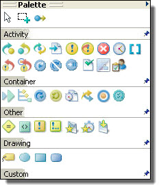
Process Developer Classic uses the same palette of icons that has been in use since Version 1.0 of Process Developer. Each BPEL construct, as specified in the WS-BPEL 2.0 specification, is represented by an icon designed by Informatica. Because the BPEL specification does not include any requirements for graphical representation, each vendor who implements the specification creates their own look and feel.
In Process Developer Classic, the palette drawers are named Activity, Container, and Other.
BPMN vs. Process Developer Classic Style Examples
The following examples show some main differences between BPMN and Process Developer Classic styles.
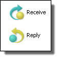
Example One: Shapes and Symbols
BPMN shapes have meanings. Circles indicate events, as shown with the receive and reply on the left below. Start events and end events have solid borders, while intermediate events have outlined borders. In Process Developer Classic, activities are categorized as basic and structured. Receives and replies are basic activities, represented by Informatica proprietary icons shown on the right.
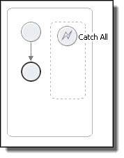
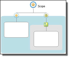
Example Two: Start, End, and Exception Events
BPMN uses event icons to indicate the start and end of a workflow (in BPMN terms a
subprocess
), as shown in the scope below on the left. The start and end events are within a hidden sequence container. You add activities between start and end. When you add a catch fault handler to the scope, the fault handler is displayed as a dotted rectangle within the scope. In Process Developer Classic, a scope starts out as an empty container. You display a fault handler with the Show Fault Handler option. Then you add a catch to it.
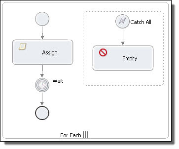
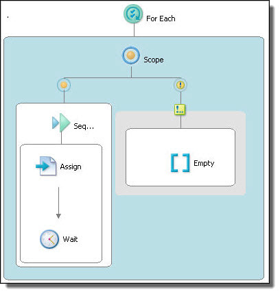
Example Three: Control Flow vs. Containers
BPEL often requires nested activities, such as those in a
forEach
, if, while, or
repeatUntil
. BPMN (on the left below) represents nesting with control flow arrows. In the
forEach
example, note also that the control flow contains an embedded (hidden) sequence. The sequence contains start and end events, and you can add activities in between. The start and end events are considered good style in BPMN, but are not strictly required, so they can be deleted if desired. Process Developer Classic displays a
forEach
container with an embedded, visible scope into which you add all activities manually.
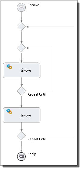
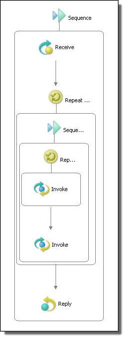
Example Four: Nested Activities
In BPMN, arrows represent control flow. Representing control flow using arrows can be easier to read than using containers, as shown in the example of nested
repeatUntil
activities. In this diagram, the parent
repeatUntil
has two children: a repeatUntil and an invoke. The child
repeatUntil
has one child: an invoke. The BPMN diagram is easier for many people to understand.
 ASK INFAPreview